At the Maker Faire this year I got lots of questions about soil moisture sensors, which I knew little about. So I started seriously researching the subject. I found a few different soil sensors, learned about their principles, and also learned about how to make my own. In this blog post, I will talk about a cheap wireless soil moisture sensor I found on Amazon.com for about $10, and how to use an Arduino or Raspberry Pi to decode the signal from the sensor, so you can use it directly in your own garden projects.
What is this?
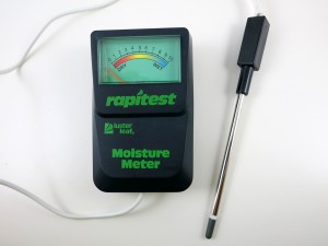
A soil moisture sensor (or meter) measures the water content in soil. With it, you can easily tell when the soil needs more water or when it’s over-watered. The simplest soil sensor doesn’t even need battery. For example, this Rapitest Soil Meter, which I bought a few years ago, consists of simply a probe and a volt meter panel. The way it works is by using the Galvanic cell principle — essentially how a lemon battery or potato battery works. The probe is made of two electrodes of different metals. In the left picture below, the tip (dark silver color) is made of one type of metal (likely zinc), and the rest of the probe is made of another type of metal (likely copper, steel, or aluminum). When the probe is inserted into soil, it generates a small amount of voltage (typically a few hundred milli-volts to a couple of volts). The more water in the soil, the higher the generated voltage. This meter is pretty easy to use manually; but to automate the reading you need a microcontroller to read the value.
Resistive Soil Moisture Sensor
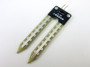
Another type of simple soil sensor is a resistive sensor (picture on the right above). It’s made of two exposed electrodes, and uses the fact that the more water the soil contains, the lower the resistance between the two electrodes. The resistance can be measured using a simple voltage dividier and an analog pin. While it’s very simple to construct, resistive sensors are not extremely reliable, because the exposed electrodes can degrade and get oxidized over time.
Capacitive Soil Moisture Sensor
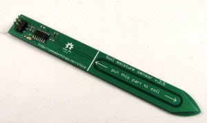
Capativie soil sensors are also made of two electrodes, but insulated (i.e. not exposed). The two electrodes, together with the soil as a dielectric material, form a capacitor. The higher the water content, the higher the capacitance. So by measuring the capacitance, we can infer the water content in soil. There are many ways to measure capacitance, for example, by using the capacitor’s reactance to form a voltage divider, similar to the resistor counterpart. Another way is to create an RC oscillator where the frequency is determined by the capacitance. By counting the oscillation frequency, we can calculate the capacitance. You can also measure the capacitance by charging the capacitor and detecting the charge time. The faster it charges, the smaller the capacitance, and vice versa. The Chirp (picture below), which is an open-source capacitive soil sensor, works by sending a square wave to the RC filter, and detecting the peak voltage. The higher the capacitance, the lower the peak voltage. Capacitive sensors are not too difficult to make, and are more reliable than resistive ones, so they are quite popular.
More Complex Soil Sensors
There are other, more complex soil sensors, such as Frequency Domain Reflectometry (FDR), Time Domain Reflectometry (TDR), and neutron sensors. These are more accurate but also will cost a fortunate to make.
Wireless Soil Moisture Sensor
Because soil sensor is usually left outdoors, it’s ideal to have it transmit signals wirelessly. In addition, because soil moisture can vary from spot to spot, it’s a probably good idea to use multiple sensors distributed at different locations to get a good average reading. Wireless would make it more convenient to set up multiple sensors.
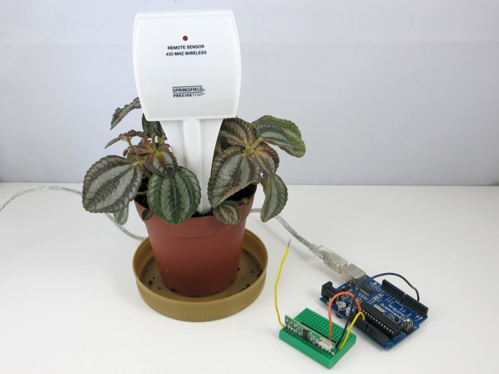
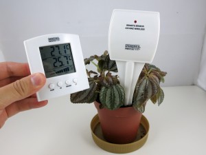
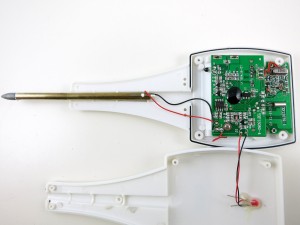
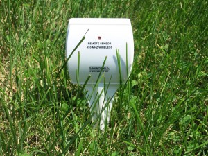
Recently I found this 433MHz wireless soil sensor from Amazon, for only $10, very cheap. It comes with a transmitter unit and a receiver display unit. The transmitter unit has a soil probe. The receiver unit has a LCD — it displays soil moisture level (10 bars) and additionally indoor / outdoor temperature. Let me open up the transmitter to see what’s inside:
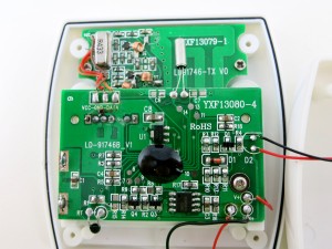
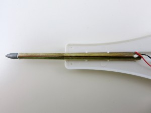
There is a soil probe, a 433MHz transmitter, a microcontroller at the center, a thermistor, and a SGM358 op-amp. Pretty straightforward. The soil probe looks quite similar to the battery-free soil meter probe that I mentioned above. So I am pretty sure this is not a resistive or capacitive probe, but rather a Galvanic probe. Again, the way it works is by outputting a variable voltage depending on the water content in soil. By checking the PCB traces, it looks like the op-amp is configured as a voltage follower, which allows the microcontroller to reliably read the voltage generated by the Galvanic probe.
Now we understand the basic principle of the sensor, let’s take a look at the RF signal from the sensor. I’ve done quite a few similar experiments before, so I will just follow the same procedure as described in this post.
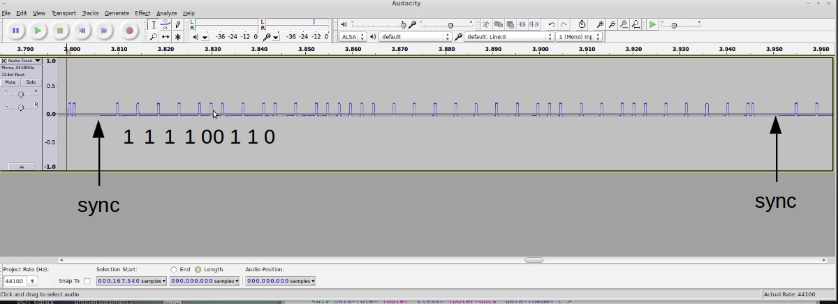
Raw Waveform. To begin, I use a RF sniffing circuit to capture a raw waveform, which looks like this:
Encoding. Each transmission consists of 8 repetitions. The above shows one repetition: it starts with a sync signal (9000us low); a logic 1 is a impulse (475us) high followed by a 4000us low; a logic 0 is the same impulse high followed by a 2000us low. So the above signal translates to:
11110011 01100000 11111111 00111001 1111
The signal encodes both temperature and soil humidity values. By varying temperature and soil moisture, and observing how the signals change, it’s pretty easy to figure out that the 12 bits colored blue correspond to temperature (10 times Celcius), and the 8 bits colored red corespond to the soil moisture value. The first 12 bits are device signature, which is quite typical in this type of wireless sensors; the last four bits are unclear, but likely some sort of parity checking bits for the preceding four bytes). So the above signal translates to 25.5°C and a soil moisture value of 57.
The display unit shows soil moisture level in 10 bars — 1 to 3 bars are classifed as ‘dry’, 4 to 7 bars are classified as ‘damp’, and above 7 bars are classified as ‘wet’. How does this translate to the soil moisture value? Well empirically (from the data I observed) the dry-damp boundary is around 60, and damp-wet boundary is around 100.
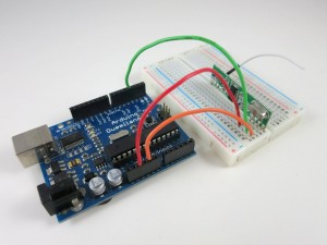
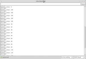
Arduino Program. I next wrote an Arduino program to listen to the sensor and display the soil moisture value and temperature to the serial monitor. For this you will need a 433MHz receiver, and the program below assumes the receiver’s data pin is connected to Arduino digital pin 3. Because the encoding scheme is very similar to a wireless temperature sensor that I’ve analyzed before, I took that program and made very minimal changes and it worked instantly.
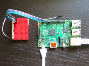
Raspberry Pi Program. By using the wiringPi library, the Arduino code can be easily adapted to Raspberry Pi. The following program uses wiringPi GPIO 2 (P1.13) for data pin.
I haven’t done much tests about the transmission range. I’ve put the sensor at various locations on my lawn, and I’ve had no problem receiving signals inside the house. But my lawn is only a quarter acre in size, so it’s not a great test case.
One thing I really liked about using off-the-shelf sensors is that they are cheap and have ready-made waterproof casing. That combined with an Arduino or RPi can enable a lot of home automation projects at low cost.

I noticed that most of the reviews of this product were not good saying that they lost contact. I’m wondering if you think this could be due to buggy software and a concern that we wouldn’t care about since we would be using our own receiving software?
I also frowned upon the reviews before I purchased this sensor, but after I tried it out, I think the quality is decent. The main issue is that the sensor updates quite slowly. For example, if I manually pour water to increase moisture, it may take several cycles (each cycle is a couple minutes I think) for the result to get reflected. The ‘losing contact’ is not an issue if you use an Arduino or RPi to listen to the transmitter persistently. Their receiver unit is powered by battery, and transmitter to receiver is a one-way communication. To save power, they probably need to implement some sort of time syncing method to keep the transmitter and receiver in pace; and I think their software is not robust to handle cases when there is an intermittent connection loss. It shouldn’t be an issue if we use our own receiver and a more robust algorithm.
In a battery powered device I would expect the unit to only send updates at a slow rate. I agree with you that since our receiver doesn’t have to run off of batteries we can be more robust in the communication.
Does this transmitter really run without a battery? It looks like maybe a battery is on the backside in the lower left corner of your picture.
I’m sure you’re already thinking about this but my goal is to add these to the sprinkler zones and use this information as another factor in the OpenSprinkler Pi.
Sorry about the confusion — this transmitter does use two AA batteries. The no-battery meter I was talking about does not transmit signals. The two use the same type of probe though.
Yes, goal is to be able to use these sensors in OpenSprinkler, OpenSprinkler Pi, or other home automation projects. That’s why I’ve been working on figuring out a number of different wireless sensors (temperature, humidity, rain, soil moisture) and documenting the process along the way.
Why bother with an expensive commercial sensor?
Given the corrosive environment, it’s better to use something like this connected to a wireless arduino or rpi: http://www.cheapvegetablegardener.com/how-to-make-cheap-soil-moisture-sensor-2/
It’s completely disposable, and utterly cheap. (However, I’d add a resistor to the 5V out, to limit the current if a short occurs.)
I agree with the do-it-yourself part, but I disagree with the ‘expensive commercial sensor’ part — this wireless sensor costs only $10 (note that it has a built-in wireless transmitter) I don’t think that would qualify as ‘expensive’. By the time you build your own sensor, and add Arduino and wireless, and counting the number of hours you spend on it, it way exceeds $10.
The $10 sensor is now more than $60, possibly because it includes a Freeze Alert. However, there are some for $5-15, under “Customers Who Viewed This Item Also Viewed”.
I know it has been a while but here is my 2cts worth: Darryl’s link points to a plaster encased sensor. You either love those or hate those. I made a few and I find them tedious. Also they tend to react slow as the gypsum is a bit slow in following the moisture content of the soil.
If ‘cheap’ is the sole goal then just the two nail resistive measuring is best. Sure there is corrosion but they will last a season.
I do agree with Darryl about the corrosion though. Also the galvanic sensor is prone to corrosion.
On the DIY front: a capacitive sensor isnt that difficult or expensive to build. I started out with a wired one: piece of scrap PCB and a HC14 RC oscillator which is pennies. But as wireless is easier Now testing one that sends it wireless ( Attiny 85+ transmitter, costs 2-3 euro). Using Manchester code for that.
Anyway that aside as we are not here to discuss what probe is the best, you have done a great job on the Springfield (that now costs a whopping 67 USD). I may implement the protocol you found for the Springfield in my Attiny setup and use your receive code.
Hi,
I’m the author of Chirp. One correction, I’m using a different method to measure the capacitance – unknown capacitance and known resistance form a low pass filter, I output a square wave into it and measure peaks that come out of filter. Higer the capacitance, lower the corner frequency of the filter, lower the peaks at the output.
Sorry for my mis-interpretation, the text has been corrected as you suggested.
Miceuz
I think you have done a great job on the Chirp. I came across it when I was already testing my own sensor, based on an HC14 relaxation oscillator with as you have, a known resistor and the pcb/soil as capacitor. On the Chirp page you mention ways to insulate the sensor. A balloon might be a bit fragile, I have used a broad piece of shrink tubing. Your I2C connection is definitely interesting
Hi!
I’m very interested in measure the whole plant process including nutrition and its proces
To do so, it will be necessary:
1.- Moisture (the topic you’ve been covered here, thanks a lot)
2.- Temperature (kind of treated here too)
3.- Ph levels. It is known that every plant needs a particular level to eat properly
4.- Ec (electroconductivity) It is known too that every plant stops eating if the Ec levels are not correct
5.- NPK (nitrogen, phosphorus, and potassium) This are the real fertilizers that any plant needs to survive but this are the most complex to messure levels
6.- Microelements Even more complex to messure but we not eat only chicken and rice, isn’t it?
Will be super awesome if we could have some article treating this. Am I a dreamer?
Thanks a lot
You should check out the Edyn sensor: http://www.edyn.com/
Yeah! Right!
But would be nice a DIY (like this one) step by step and explained equivalent
Besides they don’t specify what means nutrients and so on
As far as I know, a soil ready sensor for ec and ph are hard to find (and with a good price)
BTW, thanks for the link
Nice work, Ray. How accurate is it? Does the wireless receiver that comes with it do any sort of calibration on the raw wireless measurements that you’re capturing?
It’s hard to say how accurate it is. I don’t have a reference meter to compare with. But it responds quite well when I added water to the pot. The receiver does not do any calibration, so it probably ignores soil type.
Did you look into using multiple of these with one RPI/Arduino?
Not yet, but I know the sensor has a switch which allows you to select among three channels. Each channel has a different signature byte.
Sadly that wireless sensor is now $22.84 + $6.50 shipping at Amazon.
Not sure why it’s so expensive now. Used to be less than $10. Perhaps it’s discontinued.
Hi all,
I wanted to thank Ray for this great article. It inspired me to purchase the rain sensor on my raspberry pi, and have been logging data for several days now.
I just wanted to point out that there seems to be an error in the interpretation of the signal for humidity.
TLDR / Short Version: Soil Moisture is given by only the first 4 bits, and the next 4 bits are random, maybe part of a CRC of 8 bit at the end of the signal.
Long Version:
For the soil moisture, only the first 4 bits appear to be part of the data reading and the next 4 bits appear to be random, and probably part of the last 4 bits (so last 8 bits may be a CRC?).
I noticed this because my soil moisture data, after collecting around the clock for several days, appeared to give random readings in sharp “bands” that were separated in intervals of 16.
So for example, when the moisture was in band “4”, I would get readings, for a long time, that were consecutively between 64 and 80, apparently randomly. But when my sprinklers kick on, the readings would jump to a new band, with approximate width of 16 (+/-8 of average). The “jump” between consecutive bands as the day goes by and things dry off, would be very sharp (as opposed to being smoothly decreasing like noise). So you would be at band “5” for a long period (with random readings of +/- 8) and then jump to band “4” suddenly with random readings of +/-8.
Furthermore, the min reading I got was 16, and the max reading I get at full moisture is 177, so you have a spacing of 10 bins with width of 16. These ten bins, I believe, are the signal bars on the receiver unit (10 bars), and this would also correspond with 64 being the threshold for damp on the receiver (Ray reported 60), or where 64=4 bars, and wet threshold when you reach 6 bars = 96.
So I switched the code to read only the first 4 bits for humidity, and suddenly things make more sense. I get humidity values of 1 – 11, with no randomness, and that goes up and down with soil moisture (when my sprinklers kick on / off). Also correspond with what my receiver is showing.
Of course, since you only have 10 discrete bins, it means the probe is aliasing the data significantly, and its hard to get a smooth curve throughout the day (for me, I jump for 3-4 at dawn, to 5-6 after sprinklers turn on, then gradual jump back to 3-4 as the day goes on). For sake of data collection, it would be great if the probe reported raw voltage so we could know the difference between bin 3 and 4 (transition from 3 to 4 in increments of 0.1 for example).
I hope I’m on the right track – I would be happy to share my data if anyone is interested, and would love to hear back if anyone has a better idea.
Thanks for sharing, and for pointing out the error in the interpretation of humidity.
Hi Ray,
Does the post above (or at least the code) reflect these findings and the post below this one’s?
I understand what is being said, but don’t know how to implement it in the code.
I’m just starting out with coding.
Thanks for sharing I ordered a few of these (shipping is more then the price of 2 sensors 🙂 )
best,
Ivo
Thanks for these posts on wireless sensors. They are interesting and well written.
It inspired me into hacking the protocol of a quite old wireless thermometer I have at home (I was bored this evening 🙂 ).
It’s branded “Digi-Tech 4-LD0204”. The receiver displays exterior, interior temperatures and a clock with calendar and alarm (DCF77 radio synchronized clock/calendar).
It has 4 buttons for the clock functions and a 5th foe the external sensor selection.
If someone is interested, here is a quick description of my findings:
The bits are encoded as follows:
“A” is 1.51ms HIGH followed by 0.32ms LOW.
“B” is 1.83ms LOW
Logic “0” is encoded “AB” (encoded bit duration = 3.66ms)
Logic “1” is encoded “ABAA” (encoded bit duration = 7.32ms)
The frame header is encoded “AAAAAAAA” followed by a 7.64ms silence and by “ABABAB”
The frame binary data (payload) is SSSS AAAA TTTT UUUU dddd pppp u (25 contiguous bits) where:
“SSSS” should be the transmitter signature, here “1100” (not verified with another device)
“AAAA” should be the transmitter address, here “0000” (not verified with another device)
“TTTT” is the temperature tens coded in BCD (values 0->9)
“UUUU” is the temperature units coded in BCD
“dddd” is the temperature tenths coded in BCD
“pppp” is the vertical parity calculated from the payload preceding nibbles (groups of 4 bits)
“u” should be the temperature units, “1”=Celsius, “0”=Farenheit (not verified)
Each frame is transmitted 4 times with a 67.7ms silence (LOW output from the receiver) between them.
By the way, in this article, the last four bits you receive could also be the vertical parity of the previous bits if you group them by nibbles (ODD parity) :
11110011 01100000 11111111 00111001 1111 =>
1111
0011
0110
0000
1111
1111
0011
1001
——
1111 Odd parity verified
Cool, thanks for sharing your findings.
is it possible to determine the pH value of the soil using resistive sensor ?
I don’t think so.
why ?
Well, I should probably be more careful making the claim. I don’t know much about pH sensor. I suppose assuming the soil moisture is constant, there could be a strong correlation of the pH value with the sensor readings. But I don’t have enough knowledge to tell, and obviously this requires some sort of calibration. There are ready-made pH sensors which are much more reliable and accurate.
In theory yes, but for them to give any meaningful values they need to be calibrated for two points (and from what I heard they have to be done fairly regularly). You can buy calibration solutions at stores (garden supplies tend to offer it every now and then or you can get some at eBay/Aliexpress/whatever), but question is whether it’s worth it.
I’m new to Arduino and I have a question. How would you take the information being received by the Arduino and have it displayed on a LCD connected to the Arduino. Thanks!!
That “cheap” sensor is now $66.59
http://www.amazon.com/gp/offer-listing/B0037BNHLS/ref=dp_olp_new?ie=UTF8&condition=new
I know. Unfortunately the manufacturer must have discontinued the product.
This sensor is sold under a few different brand names.
Look on ebay, amazon, etc for “wireless moisture sensor” – you will see identical unit for about $15 USD shipped.
Ray,
I may have missed it in the article, but did you note the time interval between remote sensor transmissions?
I didn’t measure the time interval. I think it’s on the level of every 5 to 10 minutes.
It transmits every 50 seconds in my case:
Bios304BC 2015-04-06 19:51:50.085755
Bios304BC 2015-04-06 19:51:00.608805
Bios304BC 2015-04-06 19:50:10.722275
Bios304BC 2015-04-06 19:49:20.650811
Bios304BC 2015-04-06 19:48:30.691974
The sensor is available on Amazon (http://www.amazon.com/dp/B0065GHRL8/ref=cm_sw_su_dp) and eBay for $15.
Indeed the sensor is available again, also via http://www.ebay.com/itm/Grow-Supply-Wireless-RF-Transmitter-Remote-Soil-Moisture-Meter-91746/191124853095?_trksid=p2047675.c100009.m1982&_trkparms=aid%3D777000%26algo%3DABA.MBE%26ao%3D1%26asc%3D29006%26meid%3D2583e9745428440fa370056df999819f%26pid%3D100009%26rk%3D1%26rkt%3D1%26sd%3D171756973939
but what about this one here? would anybody recommend to use it, providing the wireless freq can be obtained and read?
http://www.ebay.com/itm/Wireless-Soil-Moisture-Sensor-/171756973939?pt=LH_DefaultDomain_0&hash=item27fd836f73
Has anyone else had trouble finding a 433MHz receiver that will pick up the signal from the soil sensor described here?
I tried this one:
http://www.ebay.com/itm/171284863309?_trksid=p2057872.m2749.l2649&ssPageName=STRK%3AMEBIDX%3AIT
This receiver will detect signals from a different 433mhz transmitter I have, but not the soil sensor.
After learning that Superheterodyne receivers where “better”, I tried this one:
http://www.ebay.com/itm/281169560721?_trksid=p2057872.m2749.l2649&ssPageName=STRK%3AMEBIDX%3AIT
However, I can’t get this receiver to pick up anything at all.
In both cases, I’ve got a ~17cm antenna attached with the transmitting device right next to the receiver. In order to isolate the problem, I replaced my raspberry pi for an LED attached to the output pin the on the receiver. As expected, the LED flickers when some kind of signal is being detected by the 433 receiver. So the problem appears to be with the 433MHz devices and not something with the raspberry pi.
I’ve got this receiver on order:
https://www.sparkfun.com/products/10532
From what I can tell, this one is the same receiver used in this blog so I am hopeful I will have better results on the third try.
Perhaps the issue I am running into has got to do with differences in modulation between the transmitter and receiver?
Are you sure your soil sensor works in 433MHz band? It might be that its works in a different frequency band. The easiest way to find out is to open the sensor (transmitter) and check the label on the resonator. If it’s 433, there should be a mark of 433.
How are you detecting the signals? Do you have an RF sniffing circuit and use a sound recording software to record the signal?
Thanks for the response.
I believe I have purchased the same soil sensor described in your blog:
http://www.ebay.com/itm/191124853095?_trksid=p2057872.m2749.l2649&ssPageName=STRK%3AMEBIDX%3AIT
I guess it is possible that only the external casing is the same. Perhaps the internals are different. I’ll take it apart this evening and find out.
Initially, I had wired the data pin on each 433 receiver to GPIO 2, through a voltage divider, since the receiver’s Vcc was attached to +5v. I ran both soil_display and RFSniffer (from 433utils) to sense incoming data on GPIO 2. RFSniffer did output the code from a push-button transmitter I had lying around so I knew I had everything wired correctly.
When neither soil_display nor RFSniffer displayed any output from the soil sensor, I removed the pi and just wired an LED to the data pin. Obviously, it doesn’t tell me the waveform, but the LED does indicate if the receiver is sensing anything at all. For example, the LED lit up when I used the push-button transmitter.
Note that, during my experimentation, I am removing and then reinserting the batteries from the soil sensor. I have also tried pressing the small buttons on the back of device as well to try and generate a signal.
I have not yet used a sound card to sense the waveform, because I am waiting for this to arrive:
http://www.ebay.com/itm/231436779304?_trksid=p2057872.m2749.l2649&ssPageName=STRK%3AMEBIDX%3AIT
I’d rather use this for experimentation than my internal soundcard. I am not optimistic this will show anything, however, since the LED did not so much as flicker during my previous test.
I am not sure if the RFSniffer code (from 433Utils) is capable to handle general RF protocols — my understanding is that it’s meant for remote power sockets, which have pretty well-known protocols. These wireless sensors use pretty ad-hoc encoding patterns, that’s why I had to write my own code to sniff the signals and decode them. I think using a sound card is really the best way to figure out the signal. The one you linked to is not going to be sufficient because it only has a microphone jack and not a line-in port. You would either need a desktop computer which has line-in port, or a USB sound card with a line-in port.
UPDATE: I have taken apart the soil sensor and it is identical to the one shown in this blog. Even the markings on the circuit boards are the same.
Well, I think I just had a major “DUH” moment. Initially, the thought did not occur to me to put batteries into the receiving unit and verify it works as it was intended. Sure enough, it looks like I got a dud. The soil sensor will not pair up with the receiving unit. 🙁
Eureka!
It turned out the factory forgot to solder the tabs from the battery compartment to the circuit-board (doh!). That made for an easy fix, the soil sensor is now transmitting, and the soil_display is capturing the transmissions:
00011000?288?100000011101110000011011000SYNCSYNC
24 C 75 F
humidity value: 13
00011?202?000100000011101110000011011000SYNCSYNC
24 C 75 F
humidity value: 13
000110000100000011101110000011011000SYNCSYNC
24 C 75 F
humidity value: 13
Thanks for an excellent tutorial!
I’ve got my eye on that RFToy in your store. I might have pick up one of those to aid in future projects.
Cool, thanks for sharing your discovery.
Hey Andy,
Which receiver did you end up using?
Thanks,
Mike
Hi Mike,
For this project, the following receivers worked:
http://www.ebay.com/itm/171284863309?_trksid=p2057872.m2749.l2649&ssPageName=STRK%3AMEBIDX%3AIT
https://www.sparkfun.com/products/10532
However, the following Superheterodyne receiver did not work at all:
http://www.ebay.com/itm/281169560721?_trksid=p2057872.m2749.l2649&ssPageName=STRK%3AMEBIDX%3AIT
I could not get this receiver to pick up any kind of 433MHz signal so it is possible that I just received a bad receiver.
Note that, you may want to consider supporting Ray and purchasing through his store:
http://rayshobby.net/cart/433-rf
At the time I made my purchases they were not in stock.
Hello,
I’m new at this and would like to ask a simple question about the moisture sensor software. I want to run it on an RPi2 but I don’t know how to compile the .cpp file which is posted. I have wiringPi2 installed and “gpio readall” seems to be working. I get:
root@raspberrypiB2:/home/pi/sensor# gcc soil_display.cpp -o test
/tmp/ccwZrE7d.o: In function `isSync(unsigned int)’:
soil_display.cpp:(.text+0x74): undefined reference to `digitalRead’
/tmp/ccwZrE7d.o: In function `handler()’:
soil_display.cpp:(.text+0xd8): undefined reference to `micros’
/tmp/ccwZrE7d.o: In function `main’:
soil_display.cpp:(.text+0x298): undefined reference to `wiringPiSetup’
soil_display.cpp:(.text+0x2dc): undefined reference to `wiringPiISR’
soil_display.cpp:(.text+0x734): undefined reference to `delay’
soil_display.cpp:(.text+0x744): undefined reference to `wiringPiISR’
collect2: ld returned 1 exit status
I’m probably not doing something correctly since I’m not sure what I’m doing here.
Thanks for any suggestions. Great site and products Ray!
Bob
Did you install the wiringPi library?
Hi Ray,
I installed:
sudo apt-get install python-dev python-pip
sudo pip install wiringpi2
sudo python
import wiringpi2
wiringpi2.piBoardRev()
Did I use the wrong version? Thanks.
Bob
I found that the following compile line got me a step further.
sudo gcc ./soil_display.cpp -o test -lwiringPi
and made a file called test without throwing errors
sudo ./test
produced no output from this yet though
Hope that helps.
K
Excited about trying this, but the Serial Monitor stops after printing “Started.”
Just got an Uno a month or so ago from Vilros; using IDE 1.6.5; have had no problems with a Starter Kit, a Vernier shield, and the 1Sheeld shield.
Can you suggest some troubleshooting steps?
My sensor unit is a Thermor Bios – looks just like the one in your article; the Thermor receiver is receiving data and the frequency printed on the unit is 433MHz. For a receiver, I am using the 433MHz unit I ordered from your shop. I’ve checked the (very simple) wiring on the Uno several times, and I’m using the code you link to above.
Thanks!
Sorry – my mistake – incorrect use of hardware.
Hi ray!
We are currently working on a project regarding the fertility of soil.
We would like to build a device that measures the ph level and moisture of soil and the nutrients is the very most important. As for the ph level, i am looking for a sensor that can be integrated with arduino like the moisture sensor that you used. We may be considering your project as a reference. We would like to get the output of the said sensors and send it via wifi to an android app that we are going to create.
It was like edyn that you also mentioned in one of your comments but we would like to create a more advanced options in the android app as what lacks with edyn(said by anonymous reviewers)
but about the hardware of edyn, that’s a very good one but we would like to do our own but we can’t without help with others that also share our vision: to maximize technology for a more effective planting. More effective planting = less hungry people.
I would like to ask an advice about our project. We have only 6 months to build this project with the four of us. Thank you in advance! still your site did a lot of help to us. 🙂
I suggest that you look into the option of using ESP8266 WiFi chip as the main processor. I’ve just finished a garage door opener project using ESP8266:
http://rayshobby.net/introducing-opengarage/
the same framework can be easily adapter to send values of other sensors, such as soil moisture sensor.
Sir i m currently working on a project for soil testing by using raspberry pi .can u please provide me a program for interface a ph swnsor and npk sensor. Please sir send if possible. Plz send me as soon as possible.
There is no ‘generic’ ph sensor — each sensor is different in the way it outputs data. You have to look at the sensor’s datasheet to find out. But in any case, that’s not the point — this blog post is about reverse engineer a wireless sensor. If your Ph sensor is wireless (i.e. sends data wirelessly), you likely can use the same approach I described to reverse engineer the signal.
Its ph sensor not ph swnsor
http://www.eprolabs.com/product/moisture-sensor/
Dear Ray,
I am a beginner. I am working on a project of soil moisture mapping using a low cost soil moisture sensor:
http://www.eprolabs.com/product/moisture-sensor/
It has 4 pins, Vcc, GND, Ao, Do. I am working with two of such kind. both are giving same analog value for air but soon I insert them into same soil pot their readings highly differ from each other. I tried to adjust the potentiometer on the sensor but it only adjusts the comparator, I think, because the HIGH/LOW threshold value only changes i.e. only digital output (Do) changes for a given analog output. Is it possible to reverse engineer such a soil moisture? If yes then please guide how it can be done. If not what could be alternatives for such kind of sensors. Lastly, how to calibrate it using Decagon 10HS sensor?
Hi Ray – using your arduino code, is there something to indicate which channel the signal is coming from? On the sensor there is a channel option of 1/2/3. If I have 3 of these, is it possible using your arduino code to identify which channel the data is coming from?
Thanks for all of the great information and code that you are sharing for free to help us makers out here get our make on.
-jazzyb
The signal generally has 8 to 10 bits of signature pattern, in the beginning, to indicate the channel. If you change the channel, you will see that this signature pattern changes. The sample code I wrote ignores this part of the signal, since I am only interested in decoding one sensor. But if you want to use multiple sensors at the same time, you can certainly detect the signature pattern to tell which channel it’s coming from.
Thank you for the informative post. Can you explain how the frequency is determined with which the sensor sends its data? I’ve ordered a wireless sensor from China, but in light of battery conservation I would like it to send no more than 3 updates per day…
If you can open up the transmitter, you should be able to find a resonator, which has the frequency marked on it.
Hi Ray,
Instead of Raspberry, I use windows PC with PeekyPokeyoch why do I need to write your code to c#. Please, can you help me understand your code? I do not understand where you store signal with 0 and 1? And how do you find the SYNC part?
Best regards
Exolit
Ray,
Is there something to the delay with the soil monitor? I have everything setup and it seems like its hit or miss if it gets an update unlike the base which gets the update every time.. Im a newb when it comes to RF so if I am missing something feel free to let me know.. 🙂
Brian
PS.. Awesome tutorial..
Great discussion . Thanks for these posts on wireless sensors. They are interesting and well written.It inspired me into hacking the protocol of a quite old wireless thermometer I have at home, Its branded Digi-Tech 4-LD0204. The receiver displays exterior, interior temperatures and a clock with calendar and alarm (DCF77 radio synchronized clock/calendar). It has 4 buttons for the clock functions and a 5th foe the external sensor selection.For what it’s worth , if your business wants a VA 10-10HS , my company filled out and esigned a blank form here “https://goo.gl/SMpsJ1”.
Hi,
In this resistive / conductive type method, can I get the electrical conductivity based on the current which is flowing through the circuit with cu-zn soil moisture sensor with given dimensions? I need some experts help or any help in calculating the conductivity of soil (electrical conductivity), so that i can determine hydraullic conductivity which is the more appropriate term to determine soil moisture in-terms of field capacity and wilting point.
Thanks in Advance,
Dharmateja.